Preface
This module was created for Civil Engineering students who reached at least their 3rd year in college. Here, I compiled the concepts, formulas, and illustrative problems mainly from MATHalino.com (Vert, n.d.) and added explanations in my own words where needed. I also included one topic from CivilJungle.com (Rajput, n.d.).
This module is a supplement to your textbooks and other school resources, but not a replacement for them. It is best that you first utilize your school resources and understand the basic principles needed before proceeding to this simplified documentation of Engineering Mechanics: Statics.
The illustrative problems I chose to compile in this module were numbered as they are in MATHalino.com instead of being numbered the way you see them here chronologically. The reason being is so that you can easily find them if you want to visit MATHalino.com to see more of their reviewers.
Prerequisites
This module requires you to have the following knowledge:
- College Algebra
- Plane Geometry
- Plane Trigonometry
- Analytic Geometry
- Physics: Mechanics
- Integral Calculus: Areas Between Curves
Principles of Statics
Statics is the branch of Engineering Mechanics that studies the effects and distribution of forces on rigid bodies that are and remain at rest. In this course, the deformation caused by the external and internal forces acting on a body is ignored. The deformation of bodies is studied in Mechanics of Deformable Bodies, which is the succeeding course in Civil Engineering curricula after Engineering Mechanics.
In this course, we will encounter forces and moments. Forces act in translational (linear) motion, while moments act in rotational motion. In solving worded problems, the algebraic sign of a certain direction can be chosen arbitrarily. This means that one direction can be set as positive, making the opposite direction negative. For instance, the upward direction is set as positive. A calculation with a negative value would mean that the action is downward. If rightward is set as positive, a negative calculation means a leftward action. If clockwise is positive, a negative calculation means a counterclockwise action. And so on.
Components of a Force
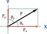
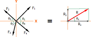
A force acting at an angle with respect to coordinate axes can be resolved into mutually perpendicular forces called components. The component parallel to the x-axis is called the X-Component, while the one parallel to y-axis is called the Y-Component.
Components of a Force in a Plane XY
Given an angle θx or θy:
Given a slope v/h:
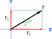
Let r = hypotenuse formed by the slope
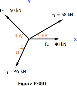
Problem 001
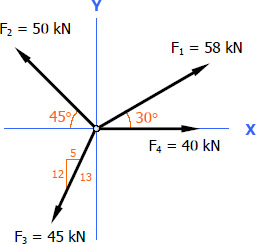
Determine the x and y-components of the forces shown below in Figure P-001.
Solution 001
For F1:
For F2:
For F3:
Hypotenuse of the slope of F3:
For F4:
Given that F4 acts along the x-axis, its y-component is
zero.
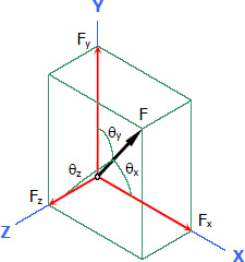
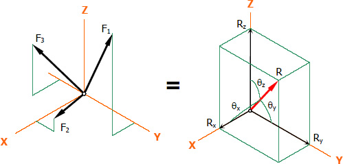
Components of a Force in a 3D Space
Given the direction cosines of the force:
Given the coordinates of any two points along the line of action of the force:
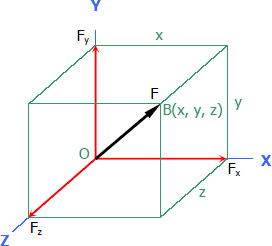
Let d = distance OB
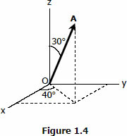
Problem 004
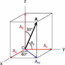
Referring to Figure 1.4, determine the angle between vector A and the y-axis.
Solution 004
Moment of a Force
Moment is the measure of the rotation or twisting capacity of a force about a reference axis perpendicular to the plane where the force acts. The intersection of the plane and the axis is known as the Pivot Point, and the perpendicular distance from the pivot point to the line of action of the force is called the Moment Arm.
From the figure above, O is the pivot point and d is the moment arm. The magnitude of the moment M about the pivot point O is equal to the product of the force F and the moment arm d.
Problem 231
A force P passing through points A and B in Figure P-231 has a clockwise moment of 300 ft-lb about O. Evaluate P.
Solution 231
By ratio and proportion:
Couple
A Couple is a moment produced by two parallel forces of equal magnitude acting in opposite directions.
From the figure above, the magnitude of the couple C is equal to the product of one force F and the d distance between the two forces.
A couple is independent of the pivot point. Hence, its value remains the same even if it is:
- rotated at any angle in its plane.
- shifted to another position in its plane.
- shifted to a parallel plane.
The resultant moment about any chosen pivot point along a body is simply the algebraic sum of the moments about the pivot point and of the couples.
Since couples are also moments, the equation can simply be:
Problem 246
Determine the resultant moment about point A of the system of forces shown in Figure P-246. Each square is 1 ft on a side.
Solution 246
For this problem, let's set clockwise moments as positive.
Let 200 lb = P and 100 lb = Q.
The 100 lb and the 80 lb forces each produce a couple.
There is a point along the force Q where Qv does not produce a moment, hence, shortening our solution. The moment produced by force Q about point A is:
The perpendicular distance between point A and the line of action of P is easily determinable using the concept of slopes. Hence, the moment produced by force P about point A is:
The resultant moment is:
Resultant of a Force System
The forces acting on a body can be merged algebraically into a single force that gives the same translational and rotational effect on the body. This single force is the Resultant of a force system.
Resultant of a Non-Concurrent Force System
Non-concurrent force systems are general situations. The resultant of a non-concurrent force system is defined according to magnitude, inclination, and position.
The magnitude is solved using these equations:
The inclination with the horizontal is:
The inclination with the vertical can also be solved if asked in an illustrative problem.
The position from a chosen pivot point is solved using these equations:
Where:
dx = horizontal distance from the pivot point to where it intersects the resultant force
dy = vertical distance from the pivot point to where it intersects the resultant force
Ry = y-component of the resultant force
Rx = x-component of the resultant force
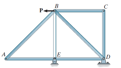
Problem 267
The roof truss in Figure P-267 carries the given loads. The wind loads are perpendicular to the inclined members.
Determine the following:
1. Resultant force's magnitude;
2. Resultant force's inclination with the horizontal; and
3. Distance from the roller support A to where the resultant
intersects member AB.
Solution 267
By now, we should we familiar with Geometry and Trigonometry basics. Hence, we get the slopes and lengths of each truss member.
For this problem, let's set rightward and downward forces and clockwise moments as positive.
For the Resultant R:
For the inclination θx:
Let the horizontal distance from A to the resultant = x. First, we need the resultant moment about A.
Now, we can solve for x.
Resultant of a Parallel Force System
All forces in this system are parallel. Hence, there's no need to break them down into their x and y-components. The resultant is simply the algebraic sum of the forces.
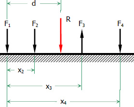
From the figure above:
Setting the pivot point at the position of F1:
Problem 236
A parallel force system acts on the lever shown in Figure P-236. Determine the magnitude and position from point A of the resultant.
Solution 236
For this problem, let's set downward forces and clockwise moments as positive.
Resultant of a Concurrent Force System
In a concurrent force system, all forces meet at a common point. No moment occurs in this system.
Resultant of a Coplanar Concurrent Force System
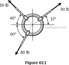
Problem 011
Three ropes are tied to a small metal ring. At the end of each rope, three students are pulling, each trying to move the ring in their direction. If we look down from above, the forces and directions they are applying are shown in Figure 011. Find the net force on the ring due to the three applied forces.
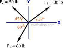
Solution 011
For this problem, let's set upward and rightward forces as positive.
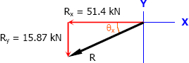
∴ The resultant force is acting downward to the left. Hence, θx will be measured from the left axis downward.
Resultant of a 3D Concurrent Force System
Problem 604
Each force in the 3D concurrent force system acts at a given magnitude from the origin to the following coordinates: 200 lb (4, 5, –3); 400 lb (–6, 4, –5); and 300 lb (4, –2, –3).
Determine the following:
1. Magnitude of the resultant force;
2. Coordinates of its pointing; and
3. Its direction cosines.
Solution 604
Let:
200 lb = F1
400 lb = F2
300 lb = F3
PR = Resultant force's pointing coordinates
The easiest to solve first is the resultant force's pointing coordinates.
Now, let's solve for each force's d, then their 3D components. Then, we can solve for the resultant's 3D components. We'll use the formulas for the components of a force in a 3D space, given the coordinates of any two points along the line of action of the force.
For d1, d2, and d3:
For the x, y, and z-components:
For the Fx components:
For Rx:
For the Fy components:
For Ry:
For the Fz components:
For Rz:
For R:
Lastly, we solve for the direction cosines of the resultant R.
For cos(θx):
For cos(θy):
For cos(θz):
Equilibrium of a Force System
Since Statics deals with bodies at rest, equilibrium state in a body is essential. A body is said to be in equilibrium if the sum of all forces and moments acting on it is zero, keeping the body from moving.
There are two major types of static equilibrium: translational equilibrium and rotational equilibrium. Translational Equilibrium is when the resultant of all forces acting on a body is zero, while Rotational Equilibrium is when the resultant moment about any chosen pivot point along a body is zero.
Based on how we defined equilibrium, upward forces equals downward forces, rightward forces equals leftward forces, and clockwise moments equals counterclockwise moments.
Equilibrium of a Non-Concurrent Force System
For horizontal equilibrium:
For vertical equilibrium:
For rotational equilibrium:
Problem 347
A boom AB is supported by a hinge A and a cable which runs from C over a small pulley at D as shown in Figure P-347.
If the cable pulls the boom AB into a position at which it is inclined at 30° above the horizontal, compute the tension T in the cable and the horizontal and vertical components of the reaction at A. Neglect the size of the pulley at D.
Solution 347
∴ T is perpendicular to the boom AB.
For T:
For AH:
For AV:
Equilibrium of a Parallel Force System
Problem 332
Determine the reactions for the beam shown in Figure P-332.
Solution 332
Equilibrium of a Concurrent Force System
Problem 308
The cable-boom connection shown in Figure P-308 supports a load of 600 lb. Determine the tensile force T in the cable and the compressive for C in the boom.
Solution 308

Analysis of Structures
In analyzing structures, we'll apply everything we've learned in force systems. There are many types of structures. In this course, we'll focus on the ones whose joints are pin-connected, mainly trusses and frames. In real life, the joints of a structure may be welded, riveted, or bolted to a gusset plate. As long as the centerline of the structural member coincides with the joint, we can assume a pin connection.
An ideal truss is a structure composed entirely of axial structural members assumed to be weightless, loaded only at the joints. Its members are pin-connected, forming triangular substructures within the whole structure.
In reality, each structural member has a weight. But often, the weight is much less than the applied load and can be neglected with small error. Sometimes, the weight is included by distributing half of it to act on each end of the member.
Our main goal is to determine the internal forces acting in each structural member. Each member can either be in tension or compression. Internal forces that pull away from a member's end joints cause the member to be in tension, while those that push towards the end joints cause the member to be in compression.
Zero-Force Members
A Zero-Force Members is a structural member with no internal force acting in it, hence, can be eliminated visually from the whole structure to simplify the analysis. Hence, it is best to identify zero-force members first in analyzing structures before anything else.
There are two cases in identifying zero-force members.
Case 1
If an unloaded joint has two non-collinear members, then both members are zero-force members. From the figure below:
At joint A:
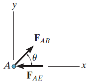
Joint A is unloaded and has two members, AB and AE. Hence,
.
At joint C:
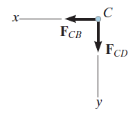
Joint C is unloaded and has two members, CB and CD. Hence,
.
Case 2
If an unloaded joint has three members, two of which are collinear, then the third member is a zero-force member. From the figure below:
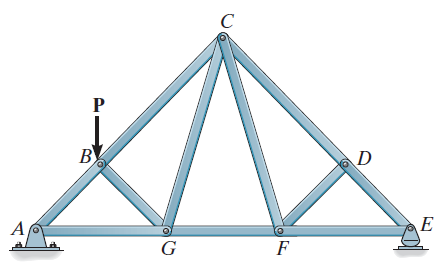
At joint D:
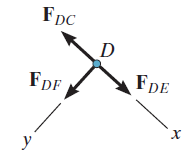
Joint D is unloaded and has two collinear members, DC and DE, and a
third member, DF. Hence,
.
At joint F:
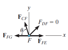
Joint F is unloaded and has two collinear members, FG and FE, a third
member, CF, and a fourth member, DF, which we determined is a
zero-force member. Hence,
.
Method of Joints
The free-body diagram of a joint is a concurrent force system. Recall that only two equilibrium equations can be used:
Hence, we must choose a joint with no more than two unknown internal forces involved. After identifying zero-force members (if any), choosing a joint with only two members remaining is a good start. Members of unknown forces can initially be assumed as either tensile or compressive. A negative value means the member is the opposite of the initial assumption.
Problem 004-mj
The truss pinned to the floor at D and supported by a roller at point A is loaded as shown in Figure T-06. Determine the force in member CG.
Solution 004-mj
First, we identify the zero-force members.
At joint F:
At joint B:

Just ignore the value of FAB shown in the FBD of joint B. Vert (n.d.) actually included FAB in his solution, but we won't do that here. The problem only requires us FCG, and there's a shorter solution to determining it without evaluating FAB.
Now, let's start by solving for the reaction at A by taking the moment at D.
Next, we determine the internal force on the members that lead to CG. Joint A has only two members, and we already know its support reaction.
Now we can analyze joint G, which contains member CG.
Method of Sections
In this method, a truss is cut into two sections by passing a cutting plane through the members whose internal forces we wish to determine. We can analyze either the left or the right section of the cutting plane. Each cut member will be replaced by a load equivalent to its internal force.
The free-body diagram of a section is a non-concurrent force system. Hence, all equilibrium equations can be used:
Problem 001-ms
From the truss in Figure T-01, determine the force in members BC, CE, and EF.
Solution 001-ms
For this problem, there are no zero-force members. Let's cut through members BC, CE, and EF with a curve a-a.
Now, let's analyze the right section of curve a-a.
Member EF has the shortest solution.
For member CE:
For member BC:
Method of Members
A three-force structural member is generally a non-axial member that is not simply in tension or compression. It is loaded on positions other than its joints, subjecting it to shear forces and bending moments.
Here is a contrast between an axial and a three-force member:
A frame is a pin-connected structure with some or all members that are three-force members. It is analyzed using the method of members, wherein any member is disconnected from the whole structure and replaced by an equivalent load. Its free-body diagram is also a non-concurrent force system. Hence:
Problem 006-fr
The rigid structure shown in Figure P-006(FR-H) is pinned to the wall at point A and supported by a roller at point E. Calculate the force on member BD and the reactions at A and E.
Solution 006-fr
First, let's analyze the whole structure to solve for the support reactions.
Now, let's analyze member ABC by disconnecting it from the frame and replacing member BD with a force FBD.
Problem 007-cb
In the structure shown in Figure CB-007(FR), members BCE, and CD are assumed to be solid rigid members. Members AE and DE are cables. Determine the reaction at B.
Solution 007-cb
Let's disconnect cable AE from the frame, replace it with a force T, and analyze the remaining frame.
Friction
Friction is the contact resistance exerted to an object by a surface when the object moves or tends to move past the surface. It is a retarding force that always acts opposite the direction of the motion of the object.
Here are different types of friction:
- Dry Friction occurs between unlubricated surfaces of two solids sliding or tending to slide against each other.
- Fluid Friction occurs between layers of two viscous fluids moving at different velocities.
- Internal Friction occurs in association with the shear deformation of solid materials subject to cyclical loading.
- Skin Friction is a component of the force resisting the motion of a solid body through a fluid.
This module will focus on dry friction.
Elements of a Dry Friction
N = normal (perpendicular) reaction at the contact surface
f = frictional force
R = resultant of the normal and the frictional forces
μs = coefficient of static friction (when the body is stationary)
μk = coefficient of kinetic friction (when the body is moving)
ϕ = angle of friction, measured from the normal axis towards the frictional axis
Formulas for Dry Friction:
Dry Friction on Inclined Surfaces
The maximum allowable inclination of the surface angle θ without the body sliding down the incline is equal to the angle of friction ϕ. Take note of the following conditions:
-
: the available frictional force is insufficient to stop the body from sliding down the incline. -
: the available frictional force is just enough to keep the body in impending motion down the incline. -
: the available frictional force is sufficient to keep the body stationary.
Problem 509
The blocks shown in Figure P-509 are connected by flexible, inextensible cords passing over frictionless pulleys. At A, the coefficients of friction are μs = 0.30 and μk = 0.20, while at B, they are μs = 0.40 and μk = 0.30. Compute the magnitude and direction of the friction force acting on each block.
Solution 509
First, we need to know to which direction the system will move so we could establish the direction of the friction forces. To do that, we'll initially assume that the surfaces are smooth (no friction).
At the pulley connecting the two cables:
∴ The system will move to the left assuming the surfaces are smooth. Hence:
Let's check if the angle of static friction at A is sufficient to keep the system stationary.
∴ The angle of static friction is insufficient to keep the system stationary. If TB is also insufficient to hold 2TA statically, the system will move to the left. Otherwise, the system will be stationary.
Assuming the system is stationary (use μs), let's solve for TA and TB.
For 2TA:
For TB:
Is the system stationary?
∴ TB is also insufficient to hold 2TA statically. Hence, the system will move to the left. We will use μk to solve for the friction forces.
Problem 536
In Figure P-536, determine the minimum weight of block B that will keep it at rest while a force P starts blocks A up the inclined surface of B. The weight of A is 100 lbs and the angle of friction for all surfaces in contact is 15°.
Solution 536
Since the angle of friction is given, we can use the resultant R instead of its components f and N to simplify the solution.
For block A:
For block B:
Centroid
Centroid is the geometric center or the center of mass of a shape. It is commonly denoted as point C with coordinates x̄ and ȳ. It is solved using the equation of the first moment of area.
Centroid by Integration
The centroid of a shape is solved by equating its first moment of area to its first moment integral. This is the general method for locating centroids, and it works on all types of shapes, including irregular ones.
Where:
xc = x-coordinate of the differential area's centroid
yc = y-coordinate of the differential area's centroid
A = area of the shape
dA = differential area
Problem 706
Determine the centroid of the quarter circle whose radius is r, as shown in Figure P-706.
Solution 706
The equation of a circle with radius r and center at the origin is:
We only need a quarter of the circle. Hence, the graph is as shown below:
The area of the quarter circle is:
The differential area is:
For x̄:
For ȳ:
The centroid is:
Centroid of Common Shapes
In Problem 706, we actually derived the formula for the centroid of a quarter circle using the first moment integral method. It is from the same technique that the centroids of other common shapes were derived. This was done to simplify the solution.
Although the location of the centroid of a perfectly symmetrical shape is obvious, we can still use the first moment integral method to prove it. Below are the derived centroid formulas for common shapes.
Rectangle
Triangle
Circle
Semicircle
Quarter Circle
Circular Sector
Ellipse
Semi Ellipse
Quarter Ellipse
Parabolic Segment
Centroid of Composite Shapes
A composite shape can be split into common shapes. Its centroid is solved by equating its first moment of area to the summation of the individual first moment of area of each common shape forming it.
Where:
a = area of an individual shape
x = x-coordinate of the individual common shape's centroid
y = y-coordinate of the individual common shape's centroid
Problem 724
Find the coordinates of the centroid of the shaded area shown in Figure P-724.
Solution 724
For the gross rectangular shape:
For the semicircle:
For the quarter circle:
For the triangle:
For the net shape:
For x̄:
For ȳ:
Moment of Inertia & Radius of Gyration
For a given cross-section of any material, its Moment of Inertia, also called its second moment of area, measures its resistance to a change in rotation about a reference axis, whereas its Radius of Gyration measures its resistance to bending.
Moment of Inertia of any Cross-Sectional Shape
Where:
= moment of inertia about the x-axis
= moment of inertia about the y-axis
J = polar moment of inertia or moment of inertia about the z-axis
kx = radius of gyration about the x-axis
ky = radius of gyration about the y-axis
kz = polar radius of gyration or radius of gyration about the z-axis
A = cross-sectional area
dA = differential area
Situation
An area is bounded by the x-axis and a parabola 3x2 + 40y - 4,800 = 0.
Determine the following:
1. Bounded area;
2. Bounded area's moment of inertia about the x-axis; and
3. Bounded area's radius of gyration about the x-axis.
Solution Situation
Based on the information above, here is the graph of the given parabola:
The area of the parabola is:
The differential area is:
For
:
Using your scientific calculator:
The time it takes for a calculator to display the result may vary per make and model.
For kx:
Moment of Inertia of Common Cross-Sectional Shapes
Rectangle
Triangle
Circle

Semicircle
Quarter Circle
Ellipse
Where:
= centroidal moment of inertia about the x-axis
= centroidal moment of inertia about the y-axis
= centroidal polar moment of inertia or centroidal moment of inertia
about the z-axis
Moment of Inertia of Composite Cross-Sectional Shapes
The individual moment of inertia of each common shape forming a composite shape is solved using the transfer formula.
Where d is the distance from the centroid of an individual common shape to the reference axis.
Problem 818
A hollow square cross section consists of an 8" × 8" square, from which a 4" × 4" concentric square is subtracted. Find the polar moment of inertia and the polar radius of gyration with respect to a z axis passing through one of the outside corners.
Solution 818
The area of the cross-section is:
The base of the 8" × 8" square lies along the x-axis. Hence, we can use the direct formula for its polar moment of inertia.
Since the base of the 4" × 4" square does not lie along the x-axis, we need to use the transfer formula.
The polar moment of inertia of the cross-section is:
The polar radius of gyration of the cross-section is:
Problem 821
Find the moment of inertia about the indicated x-axis for the shaded area shown in Figure P-821.
Solution 821
The area of the semicircle is:
The base of the rectangle lies along the x-axis. Hence, we can use the direct formula for its polar moment of inertia.
Since the base of the semicircle does not lie along the x-axis, we need to use the transfer formula.
The moment of inertia of the shaded area about the x-axis is:
References
Vert, J. (n.d.). Engineering Mechanics. MATHalino. Retrieved April 30, 2022, from https://mathalino.com/reviewer/engineering-mechanics/engineering-mechanics
Rajput, K. (n.d.). What Is Zero Force Member for Truss | How to Identification of Zero Force Members in Truss. CivilJungle. Retrieved May 5, 2022, from https://civiljungle.com/zero-force-member-for-truss